Discontinued kit - for reference only
Version 1 sYnare 3 Assembly ManuaL ( discontinued )
This vintage style synth board will give you all the great sonic possibilities of a true analog system. Although this circuit is vintage technology compared to the digital synth world, it is still preferred by seasoned professionals for tone versatility, ease of use, and responsiveness to "on the fly" patch changes. Direct control parameters are completely step-less giving you infinite control combinations. Whether its melodic tones, or the sounds of sweeps, pops, blips, you name it...... the Percussive Synthesizer kit will provide you with an endless variety of sounds.
The unit is dynamic and level dependent. There are two oscillators. Oscillator one can produce noise or an adjustable pitch. Oscillator two can generate an LFO (called SLO on the unit) or an adjustable pitch. Either oscillator can be turned off if single oscillator operation is desired. There is a filter on the unit as well, with the following controls: Tune (filter frequency), Oscillator 2 level, Sweep, Resonance, and Decay. The final amplifier section has Volume and Decay time controls. The resonance in the filter section can be turned up to get self-oscillation.
Construction notes:
- All parts should be mounted on the side of the PCB indicated by the silk screen.
- Some components must be mounted in a particular orientation on the PCB. Follow the mounting instructions carefully and read each step completely before mounting the component.
- When soldering to the PCB, it is only necessary to apply solder to the side of the board opposite to the component being soldered. The holes on the PCB are plated through so the connection will be made on both sides.
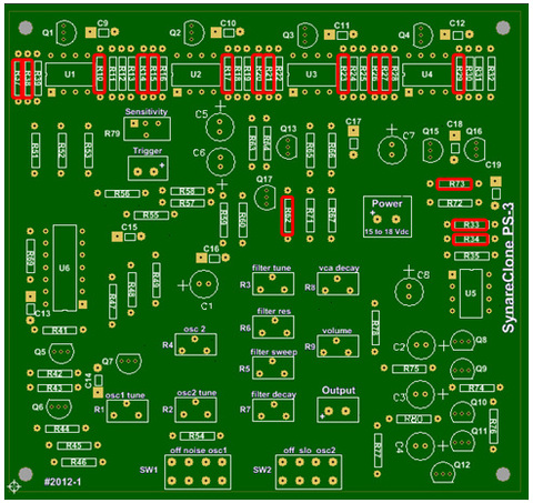
- Much time and frustration can be avoided by installing the component families on the circuit board in the order shown in the following photographs.
- To avoid misplacement of a part, pay close attention the silkscreen part designators and any polarity indication. Once the part has been soldered, it is very difficult to remove without damage to the board and/or component.
Tools Needed
- Solder
- Soldering iron with fine tip
- Wire cutters
- Wire strippers
- Volt-Ohm meter
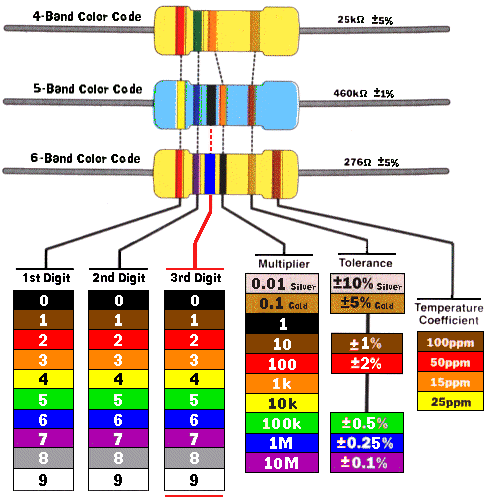
Resistor color code chart for reference
|

For color codes etc...we HIGHLY recommend
the FREE ElectroDroid app for all serious kit builders or electronics experimenters. |
Assembly Steps:
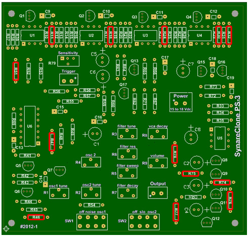
1. Insert and solder all board 220 ohm resistors (red, red, brown).
R10, 14, 15, 17, 20, 21, 23, 26, 27, 29, 33, 34, 37, 38, 62, 73
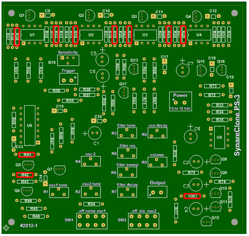
2. Insert and solder all board 10K ohm resistors (brown, black, orange – or – brown, black, black, red)
R11, 18, 24, 30, 32, 46, 47, 51, 74, 75, 76, 77, 78
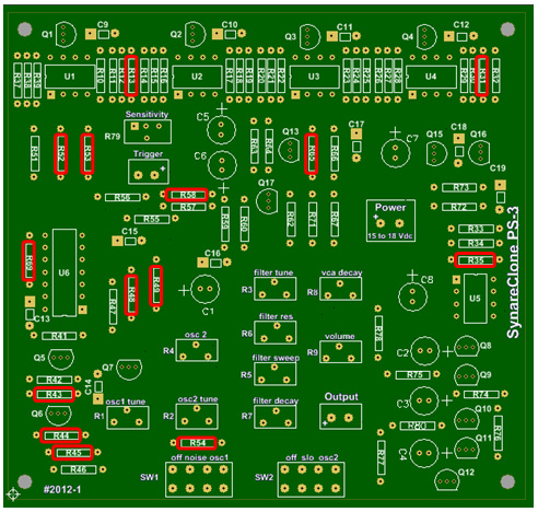
3. Insert and solder all board 100K ohm resistors (brown, black, yellow – or – brown, black, black, orange). R12, 16, 19, 22, 25, 28, 39, 41, 42, 80.
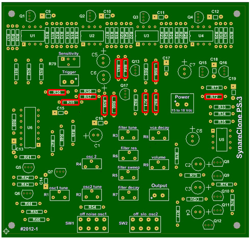
4. Insert and solder all remaining resistors.
R13, R52, R54 - 470K (yellow, violet, yellow)
R31, R58 - 2.2K (red, red, red)
R35, R43 – 1M (brown, black, green)
R44 – 22 ohm (red, red, black)
R45, R53 - 6.8K (blue, gray, red)
R48, R65 – 100 ohm (brown, black, brown)
R49, R69 – 22K (red, red, orange)
R55, R59, R71 - 220K (red, red, yellow - or - red, red, black, orange)
R56, R66 – 330K (orange, orange, yellow)
R57 – 2.7Meg – (red, violet, green)
R60, R63 – 68K (blue, gray, orange)
R64 – 820K (gray, red, yellow)
R67- 47K (yellow, violet, orange)
R72 – 1K (brown, black, red)
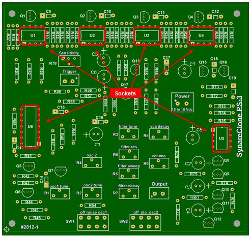
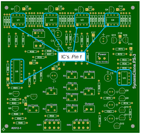
5. Insert and solder all DIP IC SOCKETS. Note: Do Not install the ICs yet, only the sockets. Some initial testing will be done before the board is populated fully with active components.
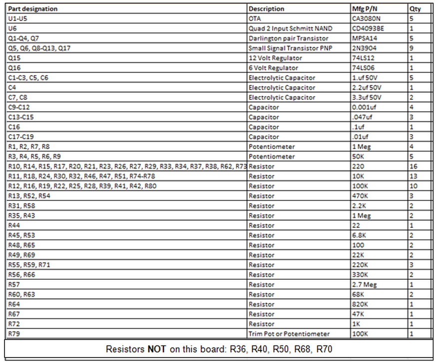
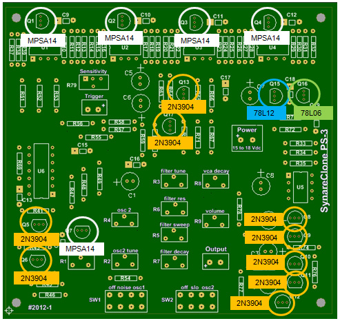
6. Insert and solder 78L12 and the 78L06 voltage regulators and the all 2N3904, and MPSA14 transistors. Mount as indicated on the silkscreen of the circuit board.
7. Insert and solder the variable resistor (trim-pot) unless you plan on mounting an external sensitivity pot.
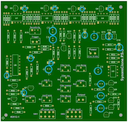
8. Insert and solder all of the capacitors. Be aware of the polarity markings on the electrolytic capacitors.
9. Wire the 1/4" audio output jack. Make sure the positive lead from the jack is soldered to the pad marked + and solder the ground lead to the right most pad.
10. Install an input jack to the board or wire your pad or trigger to the trigger location marked on the board.
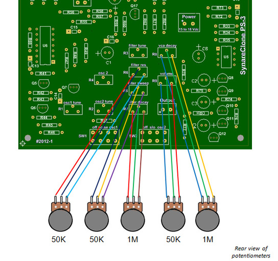
11. Install the potentiometers and the switches. There should be a one to one pin-out relationship with the pot and switch terminals to the board pads. Make sure to use enough wire length so that you can easily mount your finished board into the enclosure that you plan to use.
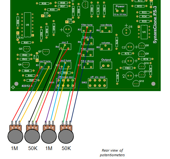
12. Using ribbon cable, solder the potentiometers away from the circuit board. The ribbon cable should be separated into groups of three wires each. Each three wire bundle should be 5 to 6 inches in length. It is easier to first solder the wires to all pots first, and then make the connections to the circuit board.
13. Using ribbon cable, solder the slide switches away from the circuit board. The ribbon cable should be separated into groups of four wires each. Each four wire bundle should be 5 to 6 inches in length. It is easier to first solder the wires to the switch terminals first, and then make the connections to the circuit board.
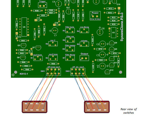
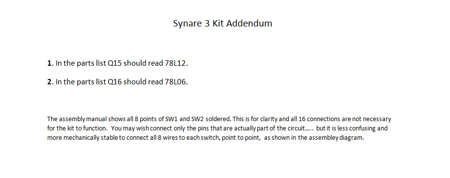
Please see addendum at bottom of webpage
14. Solder the output jack and the piezo trigger to the board. If using a drum pad or other source for the trigger, install an additional jack for this input (not included).
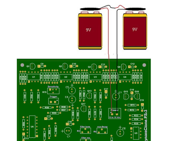
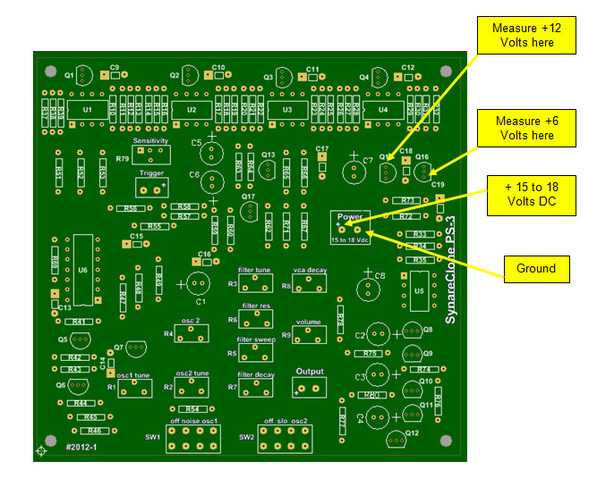
15. Connect power to the board and verify that +12 volts and +6 volts are being supplied to the circuitry. This is accomplished by first supplying 15 to 18 volts DC to the power connection on the board. This can be obtained from a low noise, well regulated power supply, or by using two 9 Volt batteries. If using batteries, use the two battery clips provided and wire them in series to provide 18 volts. With a VOM measure the outputs of both the +12 volt regulator (Q15 pin 1) and the +6 volt regulator (Q16 pin 1) referenced to ground.
16. After the assembly and power test are complete, remove the power. You may now insert the IC’s into their sockets. Please pay close attention the correct pin placement of these parts. Turn R79 (sensitivity) to the mid position. Make sure R9 (Volume) is turned up so that the output is at an audible level. Turn the remaining pots to their mid-levels. You may now experiment with all of the front panel controls to hear the various effects on the output of the synthesizer. Listed below are the front panel controls and the parameters that they adjust on the synth.
Suggestion: Until your completed board has been put into a proper enclosure, it is best to test the board and controls by securing everything down. Tape the board down on all four corners on a flat table surface, then tape down all of the pots and label their functions. This will make any testing and adjustments much easier and will give you a free hand to tap the trigger with one hand while adjusting pots with the other.
Controls:
Oscillator 1 - Pitch Source
TUNE: controls pitch of Oscillator in OSC 1 position
OFF: no function
NOISE: white noise source
OSC 1: turns on Oscillator pitch
Oscillator 2 - Pitch source and controller
TUNE: controls pitch of oscillator in OSC 2 position or speed of LFO in SLO position
OFF: no function
SLO: makes oscillator an LFO controller
OSC 2: turns on oscillator pitch (or higher speed LFO)
Filter - Sound modifier or source
TUNE: controls sound quality of an oscillator or tune (pitch) of the filter
OSC 2: controls how much LFO (Oscillator 2) affects the filter
SWEEP: determines how much pitch drop the Tune of the Filter will have
RES: controls sound quality of an oscillator or turns the Filter into a sound source
DECAY: determines how long it takes for the Sweep to effect the Tune of the Filter
Amplifier - Controls how the output will sound
DECAY: determines how long the sound will take to die out
VOL: controls the volume of the output
HAVE FUN !