
SYNARE-X SENSOR ASSEMBLY MANUAL
For Board Assembly # 110116 ONLY
This vintage style synth board will give you all the great sonic possibilities of a true analog system. . Although this circuit is vintage technology compared to the digital synth world, it is still preferred by seasoned professionals for tone versatility, ease of use, and responsiveness to "on the fly" patch changes. Direct control parameters are completely step-less giving you infinite control combinations. Whether its melodic tones, or the sounds of sweeps, pops, blips, you name it...... this Percussive Synthesizer kit will provide you with an endless variety of sounds.
Construction notes:
All parts except as indicated should be mounted on the side of the PCB indicated by the silk screen.
Some components must be mounted in a particular orientation on the PCB. Follow the mounting instructions carefully and read each step completely before mounting the component.
Parts List:
R1, 6, 8, 9, 10, 13, 20, 35, 36
Brown Black Orange - 10K
R23, 24, 25, 26, 27, 28, 29
Yellow Violet Orange - 47K
R14, 15, 16, 17, 30, 32, 33, 34
Brown Black Yellow - 100K
R5, 11
Brown Black green- 1M
R19
Orange Orange Red - 3.3K
R7
Yellow Violet Red - 4.7K
R31
Orange Orange Yellow - 330K
R4
Red Red Yellow - 220K
R2, 3
Red Red Brown - 220
R37
Yellow Violet Brown - 470
R21
Blue Grey Red - 6.8K
R12
Brown Black Red - 1K
VR1, VR3, VR5, VR6
50K Linear Potentiometer
VR2, VR4
1M Linear Potentiometer
VR7
50K Trim Pot
C1
.1 uf (may be labeled “104”)
C2
.047 uf capacitor (may be labeled “473”)
C3
.001uf capacitor (may be labeled “102”)
C4, C5
3.3 uf electrolytic capacitor
D1
IN914 diode
D2
LED
Q1
2N3904 transistor
Q2
780L05 voltage regulator
U1
CA3080 transconductance op-amp
U2, U3
LM324 quad op-amp
P1, P2, P3
Solder-less Screw Terminals
NOTE: resistors R18 and R22 are no longer used in this current board design, therefore you will
not see their part designations on the board and they are no longer packaged with the kit.
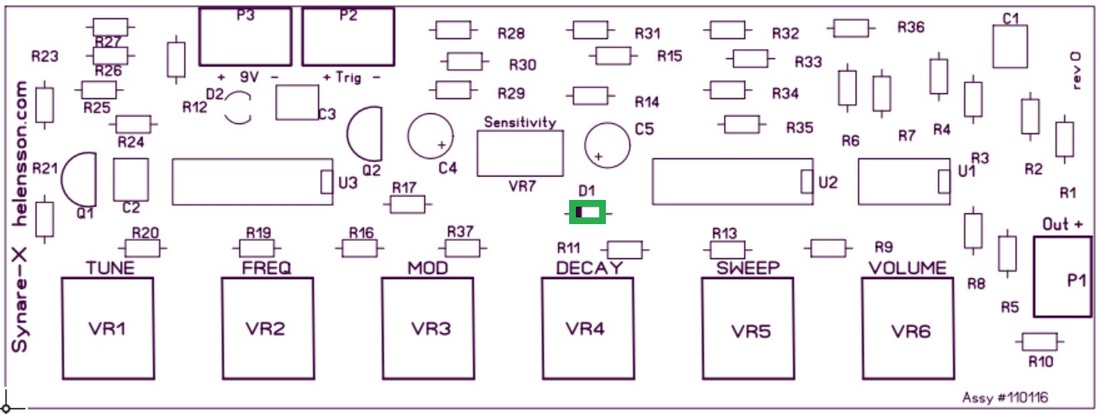
Component mounting :
When soldering to the PCB, it is only necessary to apply solder to the side of the board opposite to the component being soldered. The holes on the PCB are plated through so the connection will be made on both sides.
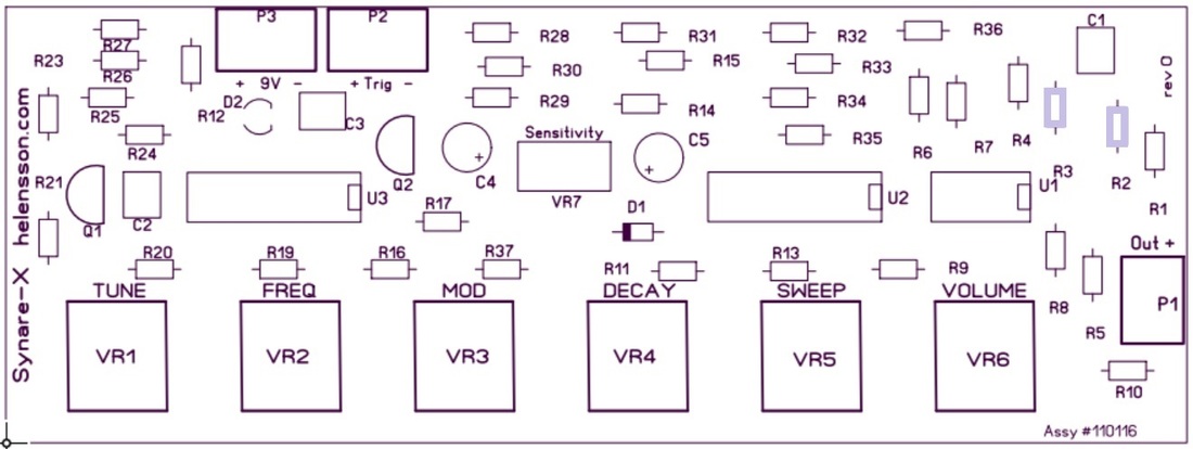
Much time and frustration can be avoided by installing the component families on the circuit board in the order shown in the following photographs.
To avoid misplacement of a part, pay close attention the silkscreen part designators. Once the part has been soldered, it is very difficult to remove without damage to the board and/or component.
For Board Assembly # 110116 ONLY
This vintage style synth board will give you all the great sonic possibilities of a true analog system. . Although this circuit is vintage technology compared to the digital synth world, it is still preferred by seasoned professionals for tone versatility, ease of use, and responsiveness to "on the fly" patch changes. Direct control parameters are completely step-less giving you infinite control combinations. Whether its melodic tones, or the sounds of sweeps, pops, blips, you name it...... this Percussive Synthesizer kit will provide you with an endless variety of sounds.
Construction notes:
All parts except as indicated should be mounted on the side of the PCB indicated by the silk screen.
Some components must be mounted in a particular orientation on the PCB. Follow the mounting instructions carefully and read each step completely before mounting the component.
Parts List:
R1, 6, 8, 9, 10, 13, 20, 35, 36
Brown Black Orange - 10K
R23, 24, 25, 26, 27, 28, 29
Yellow Violet Orange - 47K
R14, 15, 16, 17, 30, 32, 33, 34
Brown Black Yellow - 100K
R5, 11
Brown Black green- 1M
R19
Orange Orange Red - 3.3K
R7
Yellow Violet Red - 4.7K
R31
Orange Orange Yellow - 330K
R4
Red Red Yellow - 220K
R2, 3
Red Red Brown - 220
R37
Yellow Violet Brown - 470
R21
Blue Grey Red - 6.8K
R12
Brown Black Red - 1K
VR1, VR3, VR5, VR6
50K Linear Potentiometer
VR2, VR4
1M Linear Potentiometer
VR7
50K Trim Pot
C1
.1 uf (may be labeled “104”)
C2
.047 uf capacitor (may be labeled “473”)
C3
.001uf capacitor (may be labeled “102”)
C4, C5
3.3 uf electrolytic capacitor
D1
IN914 diode
D2
LED
Q1
2N3904 transistor
Q2
780L05 voltage regulator
U1
CA3080 transconductance op-amp
U2, U3
LM324 quad op-amp
P1, P2, P3
Solder-less Screw Terminals
NOTE: resistors R18 and R22 are no longer used in this current board design, therefore you will
not see their part designations on the board and they are no longer packaged with the kit.
Component mounting :
When soldering to the PCB, it is only necessary to apply solder to the side of the board opposite to the component being soldered. The holes on the PCB are plated through so the connection will be made on both sides.
Much time and frustration can be avoided by installing the component families on the circuit board in the order shown in the following photographs.
To avoid misplacement of a part, pay close attention the silkscreen part designators. Once the part has been soldered, it is very difficult to remove without damage to the board and/or component.
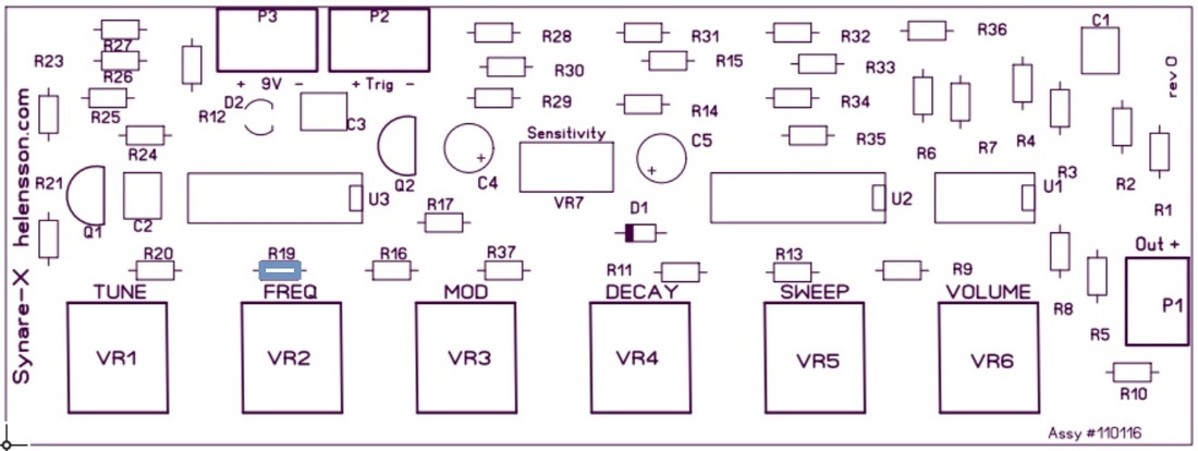
Assembly Steps:
1. Insert and solder resistors.
1. Insert and solder resistors.
10K - Brown - Black - Orange
R1, 6, 8, 9, 10, 13, 20, 35, 36
R1, 6, 8, 9, 10, 13, 20, 35, 36
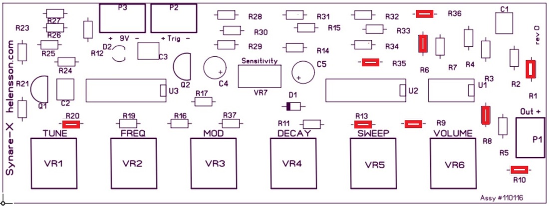
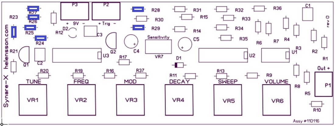
47K - Yellow - Violet - Orange
R23, 24, 25, 26, 27, 28, 29
R23, 24, 25, 26, 27, 28, 29
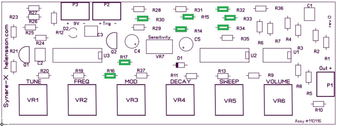
100K - Brown - Black - Yellow
R14, 15, 16, 17, 30, 32, 33, 34
R14, 15, 16, 17, 30, 32, 33, 34
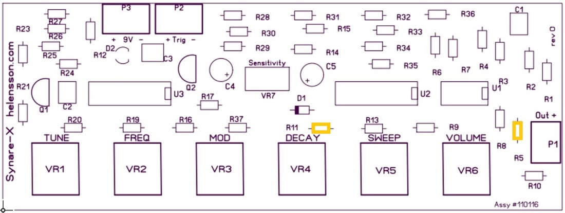
1M - Brown Black Green
R5, R11
R5, R11
3.3K - Orange Orange Red
R19
R19
4.7K - Yellow Violet Red
R7
R7
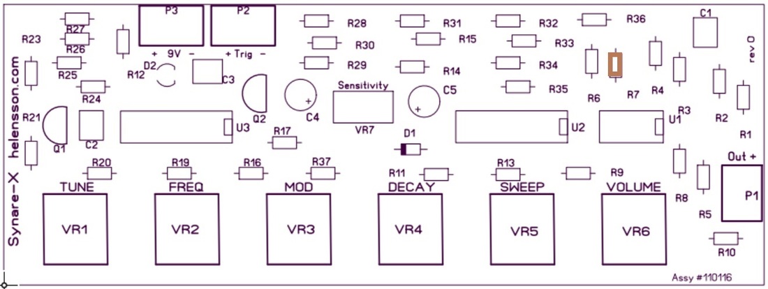
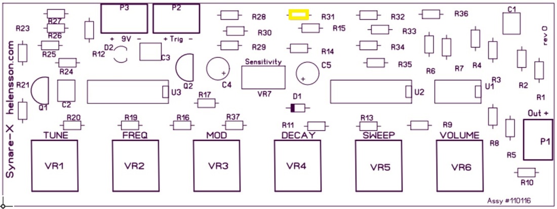
330K - Orange Orange Yellow
R31
R31
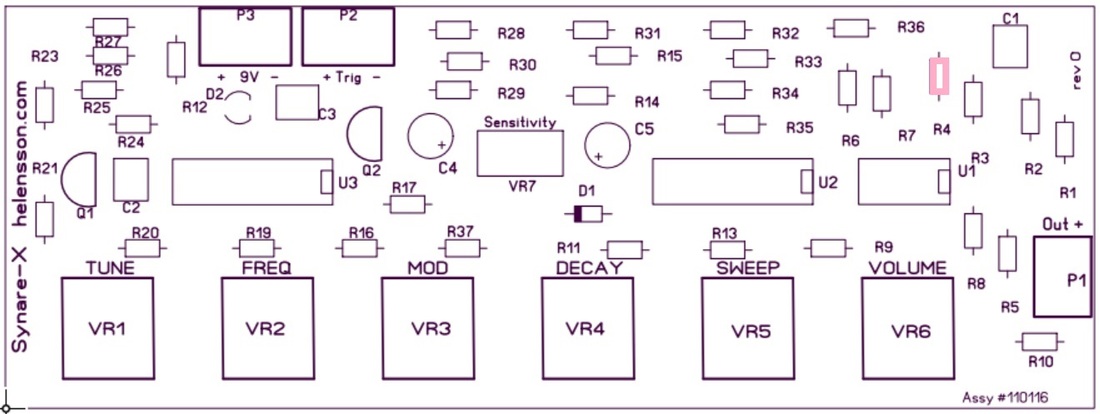
220K - Red Red Yellow
R4
R4
220 - Red Red Brown
R2, R3
R2, R3
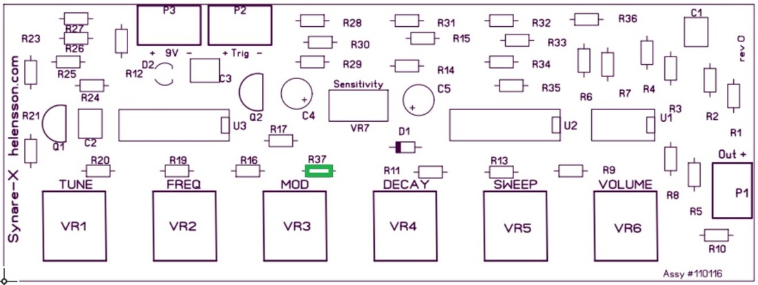
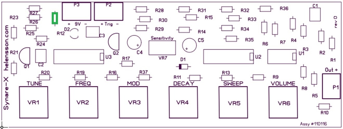
470 - Yellow Violet Brown
R37
R37
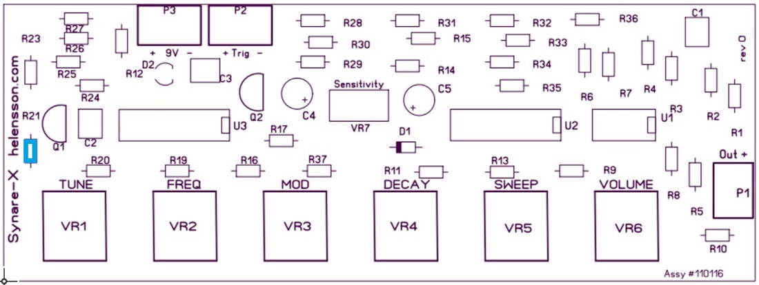
6.8K - Blue Grey Red
R21
R21
1K - Brown Black Red
R12
R12
2. Insert and solder Diode.
IN914 (observe polarity)
D1
D1
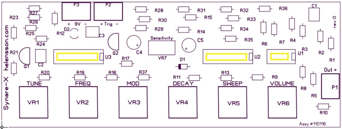
3. Insert and solder sockets for the IC's
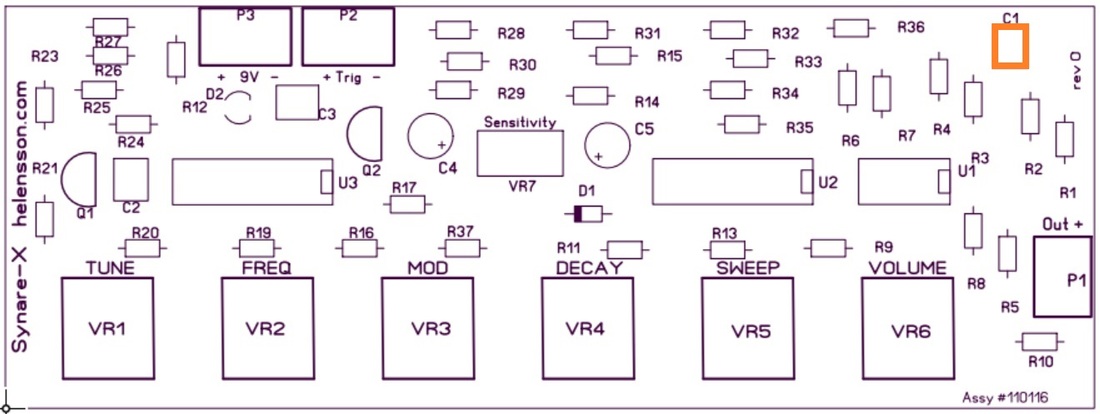
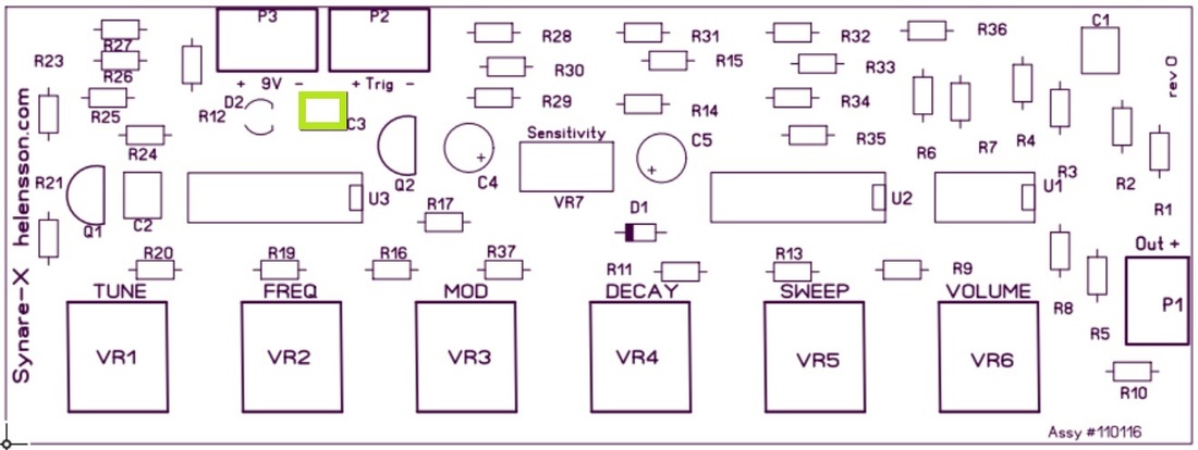
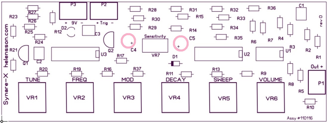
4. Insert and solder Capicitors
.1uf (may be labeled “104”)
C1
C1
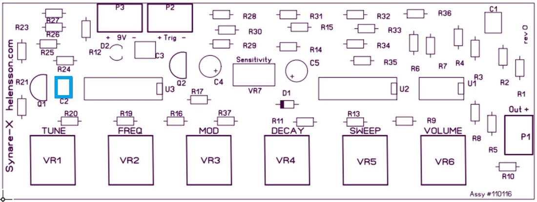
.047uf capacitor (may be labeled “473”)
C2
C2
.001uf capacitor (may be labeled “102”)
C3
C3
3.3uf electrolytic capacitor
C4, C5
C4, C5
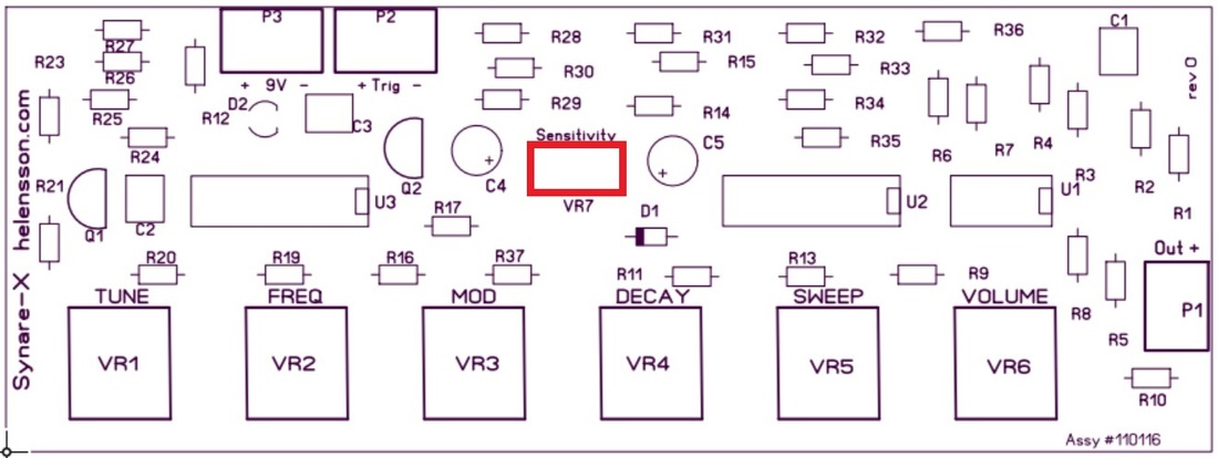
5. Insert and solder 100K TrimPot
VR7
VR7
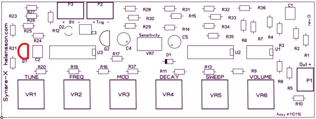
6. Insert and solder 2N3904 transistor
Q1
Q1
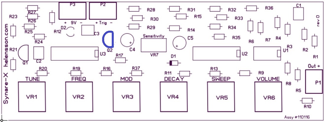
7. Insert and solder 78L05 Regulator
Q2
Q2
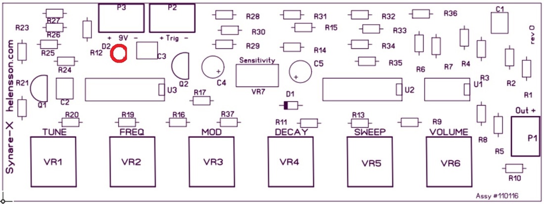
8. Insert and solder LED
D2
D2
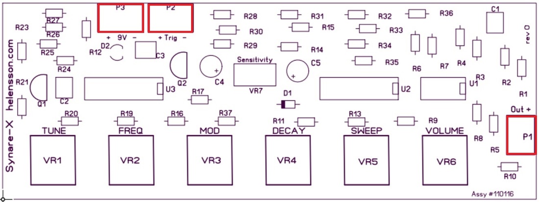
9. Insert and solder Screw Terminals
P1, P2, P3
P1, P2, P3
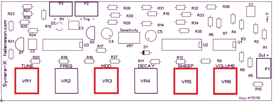
10. Insert and solder the four 50K potentiometers
VR1, VR3, VR5, VR6
VR1, VR3, VR5, VR6
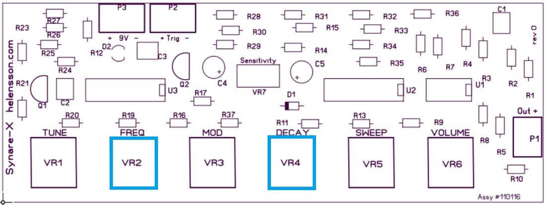
11. Insert and solder the two 1M potentiometers
VR2, VR4
VR2, VR4
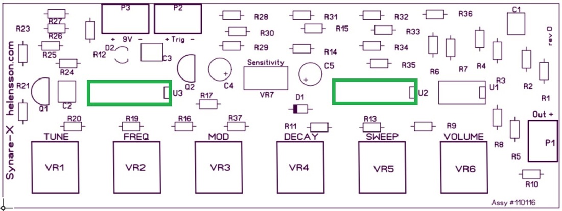
12. Insert the two LM324's into their sockets
U2, U3
U2, U3
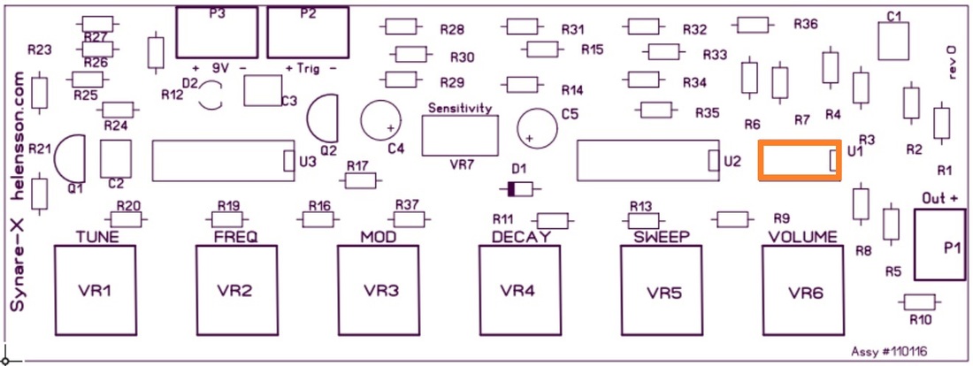
13. Insert the CA3080 into its socket
U1
U1
The Synare-x Inputs and Outputs:
P3 - Power Input ... 9 to 12 volts (DC only)
P2 - trigger input ... connect piezo here
P1 - Audio output ... connect to amp/sound system
P3 - Power Input ... 9 to 12 volts (DC only)
P2 - trigger input ... connect piezo here
P1 - Audio output ... connect to amp/sound system
The Synare-x Controls :
Tune - controls the pitch of the Oscillator
Freq - controls speed/rate of the LFO pitch control wave
Mod - controls depth of the LFO pitch control wave
Decay - controls the length of the sound
Sweep - controls range in which the oscillator sweeps
Vol - controls the output volume
NOTE: The first time you power up and test the board, make sure that the trim-pot VR7 is not fully off. Trim-Pot VR7 is used to adjust the input sensitivity of the external piezo signal. Its recommended you start with it set midway on initial setup, then adjust as needed for best sensitivity response.