synare sensor assembly manual
Percussive Synthesizer Model MPC
This vintage style synth board will give you all the great sonic possibilities of a true analog system. . Although this circuit is vintage technology compared to the digital synth world, it is still preferred by seasoned professionals for tone versatility, ease of use, and responsiveness to "on the fly" patch changes. Direct control parameters are completely step-less giving you infinite control combinations. Whether its melodic tones, or the sounds of sweeps, pops, blips, you name it...... the Percussive Synthesizer kit will provide you with an endless variety of sounds.
Construction notes:
Parts List:
R1, 6, 8, 9, 13, 20, 35, 36, Rout Brown Black Orange 10K
R23, 24, 25, 26, 27, 28, 29 Yellow Violet Orange 47K
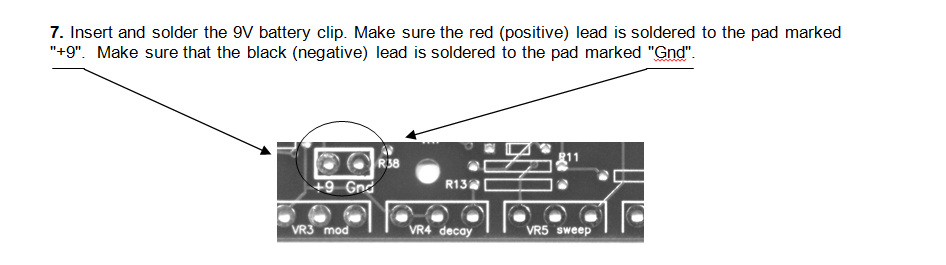
R14, 15, 16, 17, 30, 32, 33, 34 Brown Black Yellow 100K
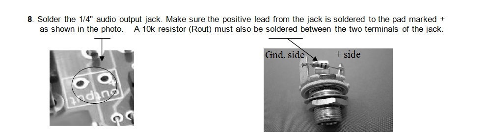
R5, 11 Brown Black green 1M
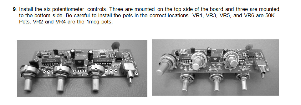
R19 Orange Orange Red 3.3K
R7 Yellow Violet Red 4.7K
R31 Orange Orange Yellow 330K
R4 Red Red Yellow 220K
R2, 3 Red Red Brown 220
R37 Yellow Violet Brown 470
R21 Blue Grey Red 6.8K
SW1 SPDT Toggle Switch
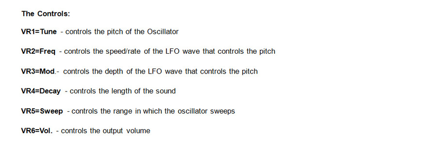
VR1, VR3, VR5, VR6 50K Linear Potentiometer
VR2, VR4 1M Linear Potentiometer
VR7 50K Trim Pot
C1 .1 uf (may be labeled “104”)
C2 .047 uf ceramic or polyester capacitor (may be labeled “473”)
C3 .001uf ceramic or polyester capacitor (may be labeled “102”)
C4, C5 3.3 uf electrolytic capacitor
D1 IN914 diode
Q1 2N3904 transistor
Q2 780L05 voltage regulator
U1 CA3080 transconductance op-amp
U2, U3 LM324 quad op-amp
9V Battery Clip
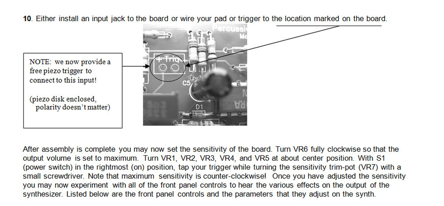
Phone Jack
NOTE: resistors R10, 12, 18, and 22 are no longer used in this current board design, therefore you will
not see their part designations on the board and they are no longer packaged with the kit.
Component mounting :
This vintage style synth board will give you all the great sonic possibilities of a true analog system. . Although this circuit is vintage technology compared to the digital synth world, it is still preferred by seasoned professionals for tone versatility, ease of use, and responsiveness to "on the fly" patch changes. Direct control parameters are completely step-less giving you infinite control combinations. Whether its melodic tones, or the sounds of sweeps, pops, blips, you name it...... the Percussive Synthesizer kit will provide you with an endless variety of sounds.
Construction notes:
- All parts except as indicated should be mounted on the side of the PCB indicated by the silk screen.
- Some components must be mounted in a particular orientation on the PCB. Follow the mounting instructions carefully and read each step completely before mounting the component.
Parts List:
R1, 6, 8, 9, 13, 20, 35, 36, Rout Brown Black Orange 10K
R23, 24, 25, 26, 27, 28, 29 Yellow Violet Orange 47K
R14, 15, 16, 17, 30, 32, 33, 34 Brown Black Yellow 100K
R5, 11 Brown Black green 1M
R19 Orange Orange Red 3.3K
R7 Yellow Violet Red 4.7K
R31 Orange Orange Yellow 330K
R4 Red Red Yellow 220K
R2, 3 Red Red Brown 220
R37 Yellow Violet Brown 470
R21 Blue Grey Red 6.8K
SW1 SPDT Toggle Switch
VR1, VR3, VR5, VR6 50K Linear Potentiometer
VR2, VR4 1M Linear Potentiometer
VR7 50K Trim Pot
C1 .1 uf (may be labeled “104”)
C2 .047 uf ceramic or polyester capacitor (may be labeled “473”)
C3 .001uf ceramic or polyester capacitor (may be labeled “102”)
C4, C5 3.3 uf electrolytic capacitor
D1 IN914 diode
Q1 2N3904 transistor
Q2 780L05 voltage regulator
U1 CA3080 transconductance op-amp
U2, U3 LM324 quad op-amp
9V Battery Clip
Phone Jack
NOTE: resistors R10, 12, 18, and 22 are no longer used in this current board design, therefore you will
not see their part designations on the board and they are no longer packaged with the kit.
Component mounting :
- When soldering to the PCB, it is only necessary to apply solder to the side of the board opposite to the component being soldered. The holes on the PCB are plated through so the connection will be made on both sides.
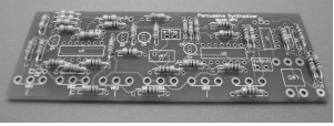
- Much time and frustration can be avoided by installing the component families on the circuit board in the order shown in the following photographs.
- To avoid misplacement of a part, pay close attention the silkscreen part designators. Once the part has been soldered, it is very difficult to remove without damage to the board and/or component.

For color codes etc...we HIGHLY recommend
the FREE ElectroDroid app for all serious kit
builders or electronics experimenters.
the FREE ElectroDroid app for all serious kit
builders or electronics experimenters.
Assembly Steps:
1. Insert and solder all board resistors.
1. Insert and solder all board resistors.
2. Insert and solder the diode (D1) . note: the diode is polarity sensitive. Mount with its band facing in the same direction as shown on the silk screen of the circuit board.
3. Insert and solder all DIP IC sockets, afterwards, install the chips into the sockets or wait until all other parts have been soldered. note: All ICs are polarity sensitive. Mount with the IC's notch facing in the same direction as shown on the silk screen of the circuit board. Installing these components incorrectly can destroy them.
3. Insert and solder all DIP IC sockets, afterwards, install the chips into the sockets or wait until all other parts have been soldered. note: All ICs are polarity sensitive. Mount with the IC's notch facing in the same direction as shown on the silk screen of the circuit board. Installing these components incorrectly can destroy them.
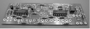
Photo shown does not show sockets installed, but you should use the free sockets provided
4. Insert and solder 78L05 voltage regulator and the 2N3904 transistor. Mount as indicated on the silk
screen of the circuit board.
5. Insert and solder the variable resistor (trim-pot).
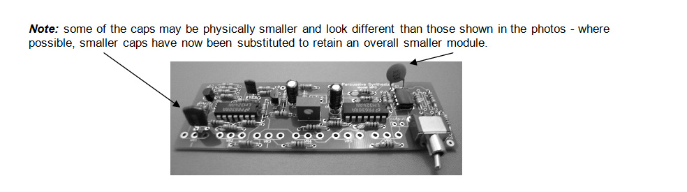
6. Insert and solder all of the capacitors and the toggle switch.